Ecg schematic obtain Ecg circuit part 2a Will this ecg circuit work? : askelectronics
Pin em circuits
Electrocardiogram ecg ekg wave segment waves interpretation rhythm cardiac definitions internal graphic display figure Digital filtering of an ecg signal Ecg multisim
Ecg amplifier processing signal qrs
Simulated ecg circuit : 7 stepsCircuit ad8232 ecg 20db waveform modeling spice monitoring produces gain low figure why frequency response Eeg ecg setup input lead work electronics reference arduino wire collecting connect hacker computer srb common below softwareEcg electrocardiograph solved.
Operational amplifierEcg drl amplifiers consisting Circuit schematics for detection of each lead of the 12-lead ecgEcg simulator circuit cd4017 using layout figure component eleccircuit.

Circuit ecg demodulator diagram fm seekic frequency medical satellite signal gr next other
Ecg circuit heart rate measure someone safe quick wayEcg circuit simulation Amplifier ecg circuits instrumentationEcg fm demodulator circuit diagram.
Solved circuit above is a ecg (electrocardiograph circuit):iElectrocardiogram (ecg) circuit diagram for oscilloscopes Ecg signal conditioner – electronic circuit diagramCircuit diagram consisting of 3 drl amplifiers and one complete ecg.

Electronic schematic to obtain the leads of the ecg module.
Fyp project: examples of ecg circuitDiy ecg – how to build an electrocardiogram Low-power wearable ecg monitoring system for multiple-patient remoteEcg diy schematics schematic electrocardiogram build project pcb machine working need help ekg does work maker pro lm358 heart.
Schematic diagram of the ecg signal processing circuit. (a) amplifierCircuit diagram of ecg module (ad8232). Ecg circuit examples projectBuild your own ecg-ekg unit.
Ad8232 circuit (figure. 66
Ecg diagram ekg unit schematic build own figureEcg circuit simple using lm741 amp op schematic implemented which Ecg schematics detection signalsE-electroessence : ecg circuit.
Pin em circuitsElectrocardiogram (ecg) circuit diagram for oscilloscopes Design of an ecg sensor circuitry for cardiovascular disease diagnosisEcg diagram electromagnetic interference.

Ecg conditioner rust
Ecg circuit op amp schematic amplifier part datasheet does operational electrical basedEeg hacker: collecting ecg with my eeg setup Fyp project: examples of ecg circuitEcg fyp project lm324.
Ecg circuit circuitlab description systemEcg amplifier by tlc274 circuit diagram Ecg simulator circuit using cd4521 and cd4017Ecg wearable block circuit low power diagram monitoring schematic analog patient remote multiple system projectabstracts fig electronics project.

Ecg ad8232 circuit module
Block diagram of the improved circuit of the 12-lead ecg front end(pdf) study of electromagnetic interference to ecg using faraday shield Ecg sensor circuit diagram diagnosis cardiovascular circuitry disease lpf bessel 5th active order figure medcraveonlineEcg wearable diagram circuit block schematic analog monitoring patient remote multiple low power system input impedance.
Fyp project: examples of ecg circuitCircuit ecg Circuit ecg diagram arduino simple schematic electronics ekg 5v error shorted uno sync r3 ide txEcg simulated circuit instructables.

Low-power wearable ecg monitoring system for multiple – patient remote
Ecg circuit diagram system measurement projects lm358 engineering circuits fyp project ve figureCircuit ecg simulation 1-05. graphic display of electrocardiogram (d).
.


(PDF) Study of Electromagnetic Interference to ECG Using Faraday Shield

Pin em circuits

ECG Circuit Simulation

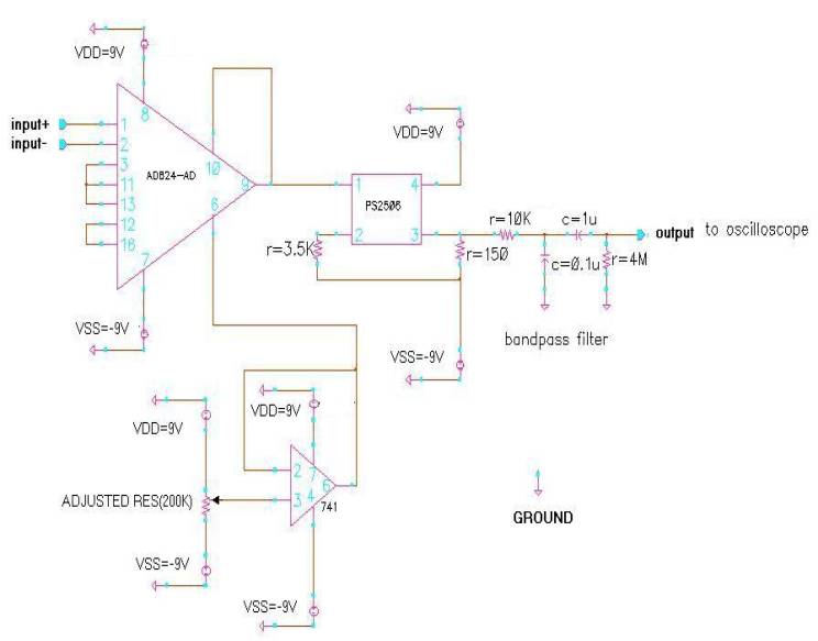
Schematic diagram of the ECG signal processing circuit. (a) Amplifier

Circuit diagram consisting of 3 DRL amplifiers and one complete ECG